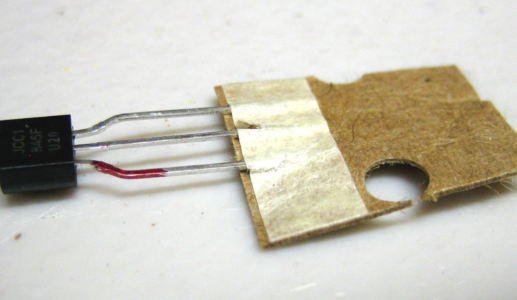
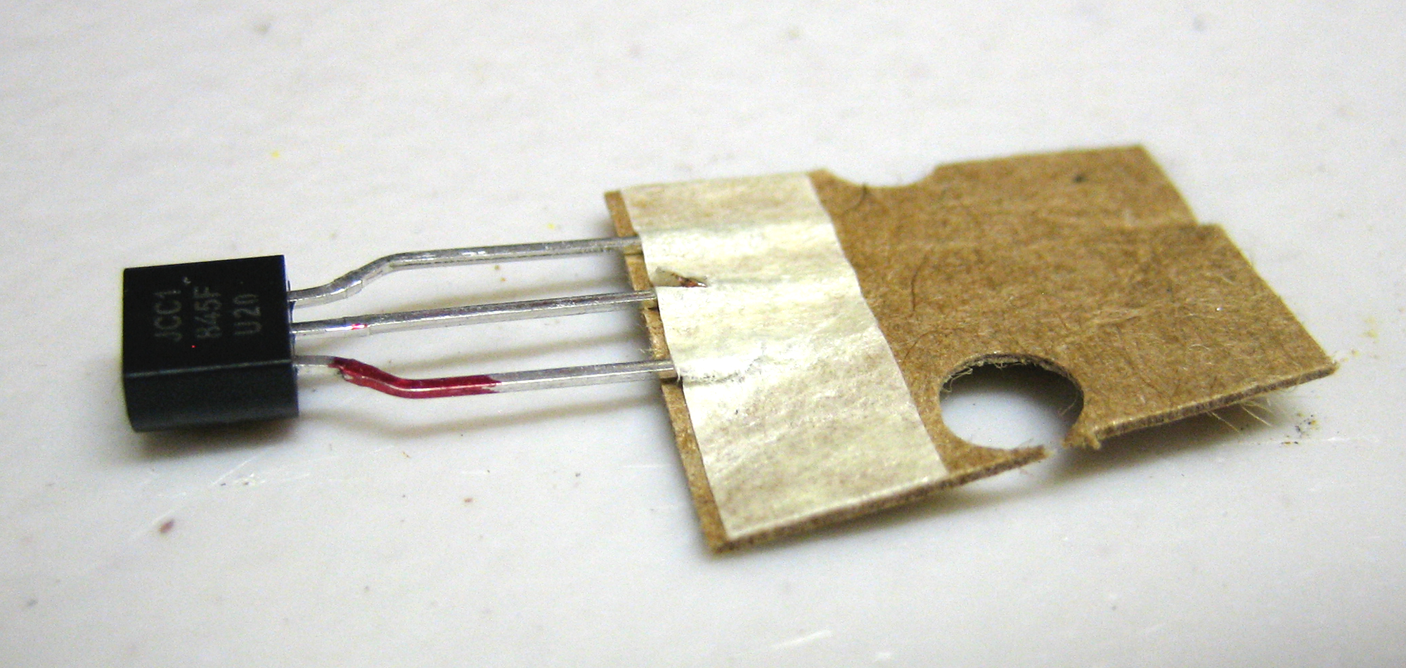
The new transistors and capacitors from DigiKey arrived and the process of swapping out got started very quickly. On the right you can see one of the new transistors. Note that I have marked the “E” lead with a touch of red. This helps me remember that the E lead goes into the E hole on the circuit board.
Transistor leads are E for Emitter, C for Collector and B for Base. In this case the configuration is E-C-B and this is very important. You have to make sure the transistor configuration matches the hole pattern in the circuit board. E-C-B transistors easily go into E-C-B holes. You can put them into E-B-C holes, but it requires a lot of careful lead bending. It isn’t easy.
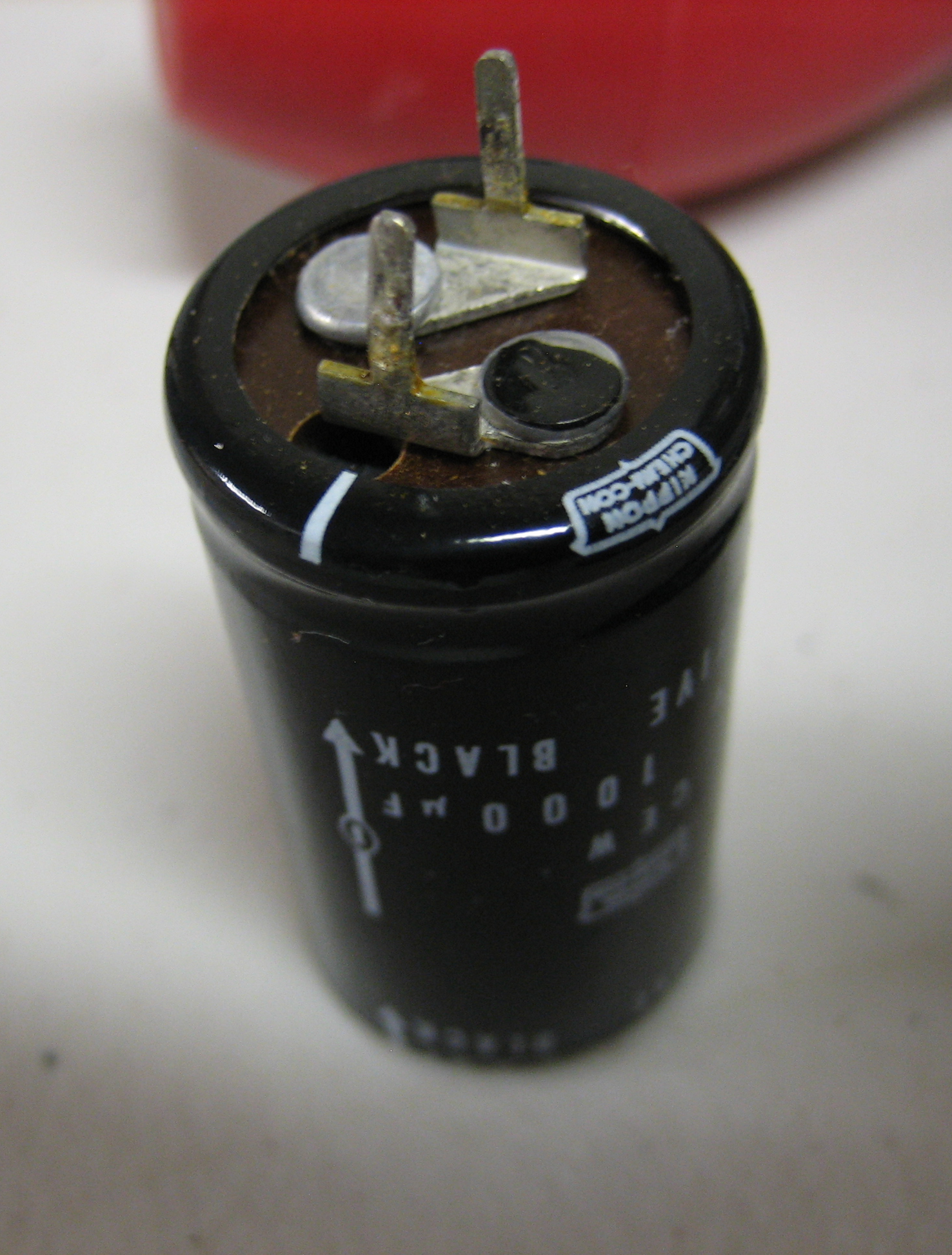
The photo on the right shows shows one of the old primary condensers that I removed and replaced with new pieces. Unfortunately, direct replacements are not available for this model so I had to use substitutes. This one is a 1000uf 35v condenser which I replaced with 1000uf 50v ones. They are fairly large and easy to work with, although the new capacitors are physically smaller.
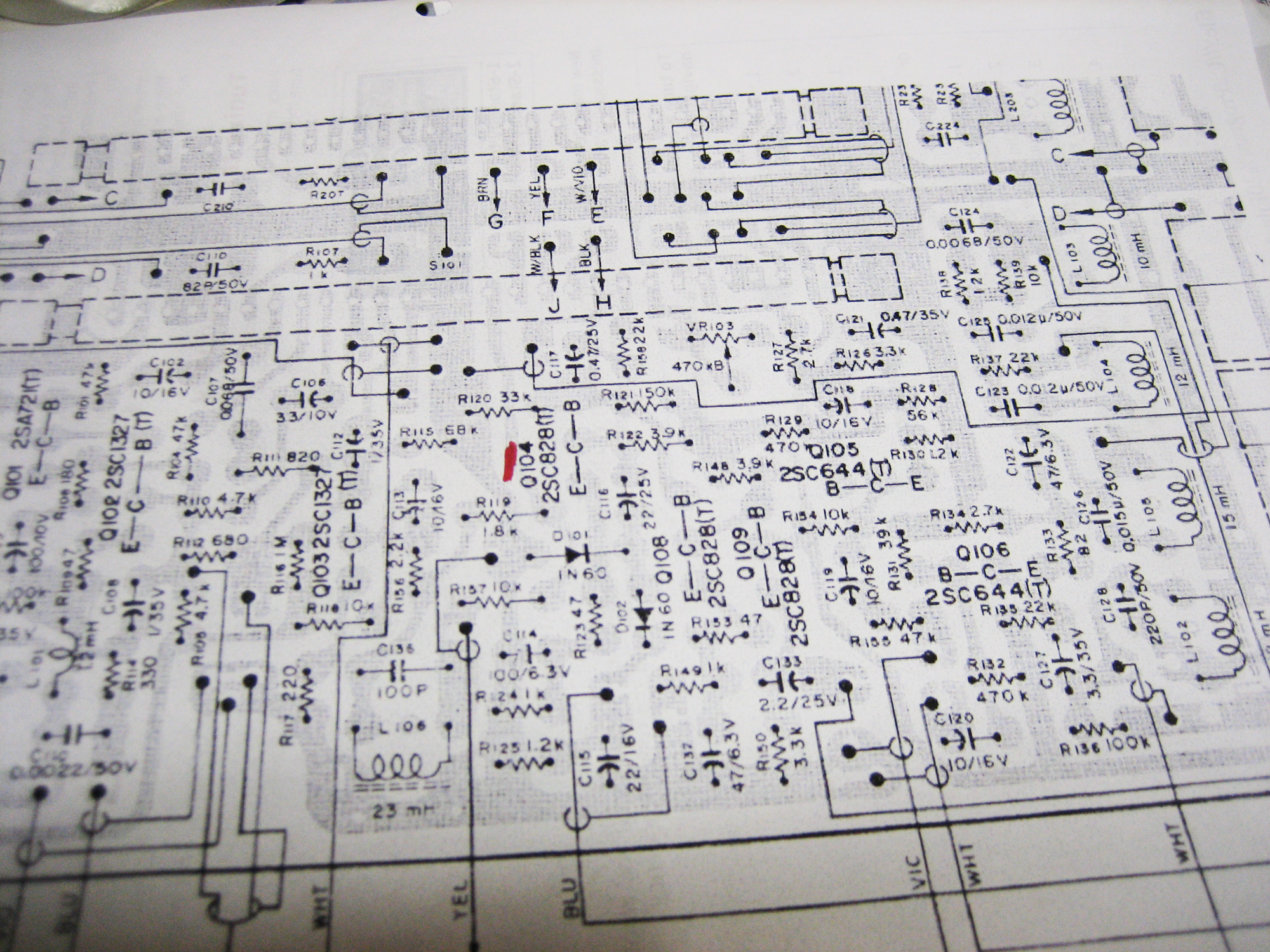
Oh, boy, let me tell you …. this is what the circuit diagram for the A360S’s main board looks like. It takes some studying and contemplation to find the parts noted on the diagram. You should see a little red mark near the center of the photograph. This is the location of the Q-104 transistor. Once I found it on the diagram all I had to do was locate it on the circuit board.
That took some time.
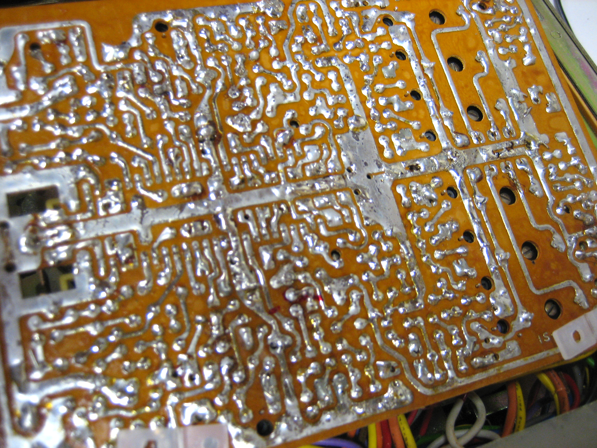
Finding the transistor on the circuit board was much more of an adventure. On the right you can see all the hand-soldered connections. Three of those are for Q-104.
I spend a lot of time wondering which was which.
In addition to Q-104 I had to replace Q-204, Q-103 and Q-203. The 100 series are for one stereo channel which the 200 series are for the other channel. Once found a transistor for, as an example, the right channel it was easier to find the matching transistor for the left channel. The circuitry for the channels are mirror images of each other.
One nice thing about the TEAC A360S circuit boards is that the component locations are all marked. Somewhere in the jungle that you see on the right is Q-104. With some extra light and a magnifying lens it was almost easy to find the right transistor.
Once I found the transistor all I had to do was find the solder points on the other side of the board. Nothing to it!
Not true. There’s a lot to it. Some of those solder points are extremely difficult to find. But once they were found it was a relatively easy task to de-solder the old transistors and capacitors and replace them with new ones.
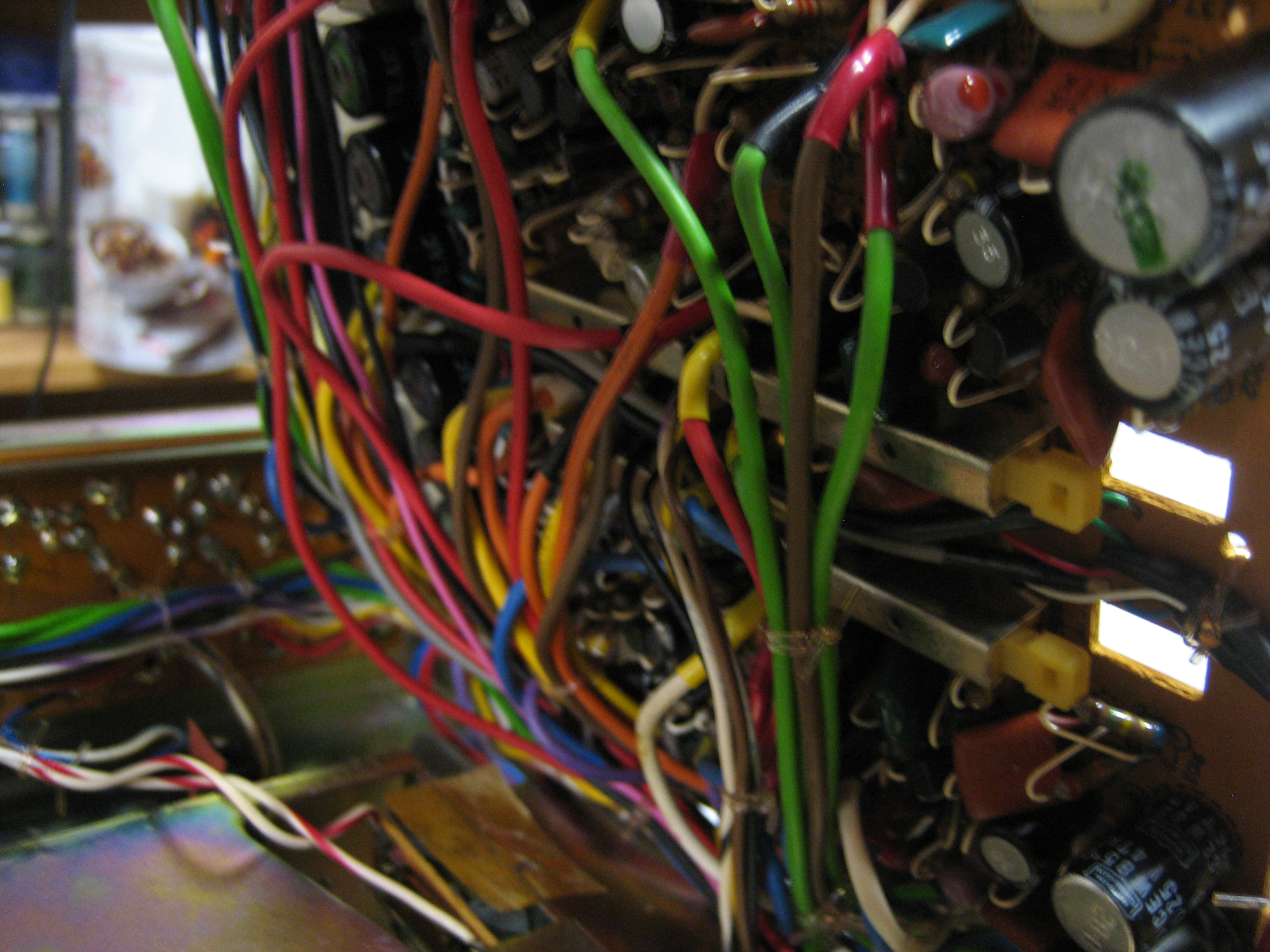
Make no mistake, this is not easy. I certainly do not suggest trying this sort of work if you haven’t done it before. There are loads of safety precautions you have to take. It is no uncommon to get shocked by a capacitor that is not fully discharged. It is a memorable experience. Needless to say, soldering safety is paramount. A mistake can result in burns, at best, or a fire at worst. That is why you must not consider these posts to be “how-to’s”. They are not that. I am posting stories about my adventures.
All that being said, I was able to replace 4 transistors and 2 capacitors. Did they do the job? Is the A360S cassette deck repaired?
We will see about that!